services@annoorlabs.com     +91 9908056677  +91 7093910033
Instagram Facebook Whatsapp Youtube Twitter linkedin

"Understanding the Benkelman Beam Deflection (BBD) Method for Pavement Evaluation"

ADMIN
/
2024-07-06
Understanding the Benkelman Beam Deflection (BBD) Method for Pavement Evaluation Pavement quality plays a crucial role in determining the longevity and performance of roads. Whether you're a student, civil engineer, architect, contractor, or a professional involved in construction, knowing how to evaluate the strength of pavements is essential for ensuring durable and high-quality roads. One widely used and trusted method for assessing the structural integrity of flexible pavements is the Benkelman Beam Deflection (BBD) Method. This article delves into the significance of the BBD Method, explaining how it is performed, who benefits from it, and why it’s crucial to the success of construction projects. It will also highlight how ANNOOR Test Labs and Engineering Services Pvt. Ltd. can assist in conducting this test to improve construction outcomes.     What is the Benkelman Beam Deflection (BBD) Method? The Benkelman Beam Deflection Method is a non-destructive testing method used to measure the deflection of flexible pavements under a loaded truck or vehicle. The method is primarily used to assess the residual life of pavements and helps in designing overlay thickness for road strengthening. IS Codes: The BBD Method is performed according to IS: 8888 (Part 1), which provides guidelines for conducting deflection measurements of flexible pavements.     Why is the BBD Test Important? Evaluates Pavement Strength and Durability: The BBD Method helps assess whether a road is strong enough to withstand traffic loads or requires rehabilitation. By measuring deflection, civil engineers can determine the load-bearing capacity and remaining life of the pavement. Prevents Early Road Failures: Without proper pavement evaluation, roads may deteriorate prematurely, leading to increased maintenance costs and potential safety hazards. This method ensures that roads are constructed to last longer by identifying weak areas before they become problematic. Guides Design for Pavement Strengthening: The data gathered from this test aids in designing appropriate overlay thickness to strengthen roads, ultimately reducing rehabilitation costs and improving the pavement's performance over time.     How to Perform the BBD Test? Preparation: 
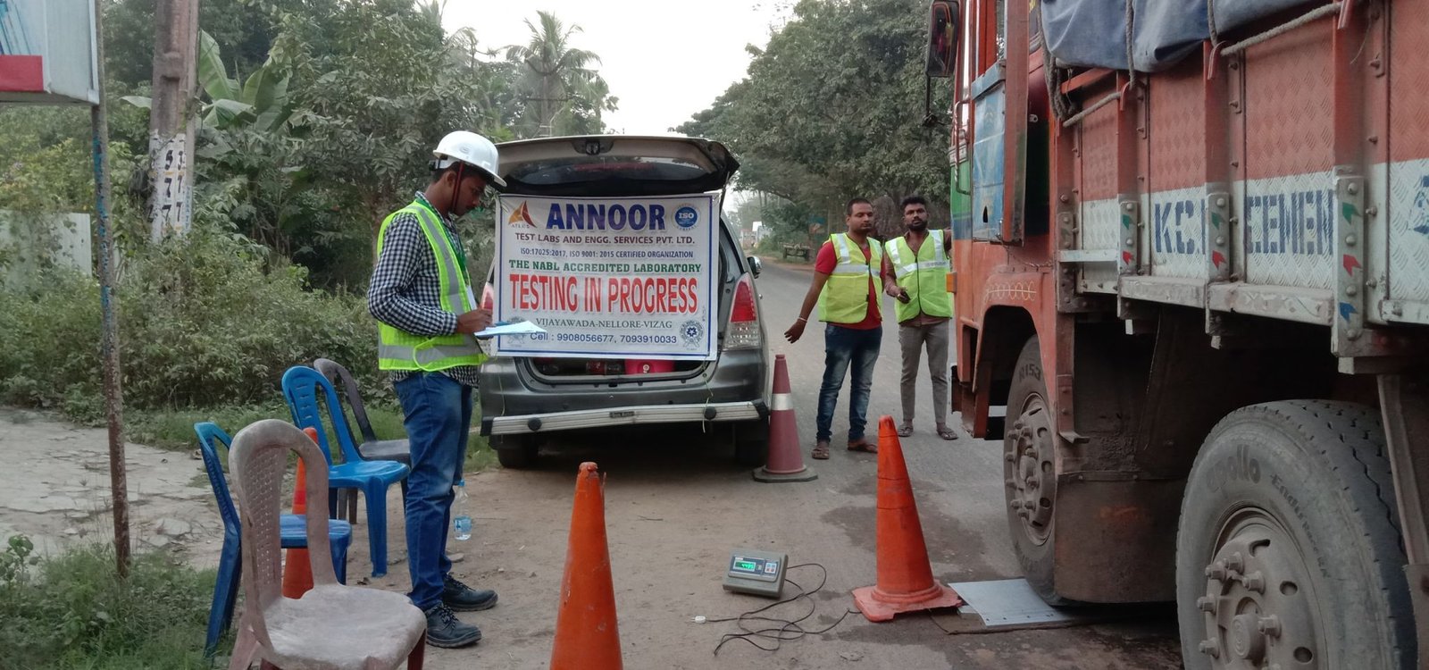
A fully loaded truck (typically 8170 kg) is placed on the pavement, and the Benkelman Beam is positioned under the rear axle. Deflection Measurement: As the truck moves away from the testing point, the beam measures the amount of deflection the pavement experiences. Recording Results: The maximum deflection is recorded, and calculations are made to assess the strength and structural capacity of the pavement. Data Interpretation: Based on the deflection values, civil engineers determine whether the pavement needs rehabilitation or is fit for use. They can also calculate the required thickness of overlays to extend the pavement’s life. Who Will Benefit from the BBD Test? Students and Civil Engineers: Gain practical knowledge on how to evaluate road conditions and strengthen their designs. Contractors and Builders: Ensure the roads they construct will perform as expected and reduce the chances of premature failures. Architects and Construction Professionals: Incorporate data-driven decisions into their designs to ensure roads last longer with minimal maintenance. By working with ANNOOR Test Labs and Engineering Services Pvt. Ltd., these professionals can access high-quality pavement evaluation services using the BBD Method, helping to ensure that construction projects are executed effectively.         What Happens if the BBD Test is Not Performed? Premature Road Failures: Without proper evaluation, roads are more likely to develop cracks, potholes, and other structural failures. Increased Maintenance Costs: Regular maintenance becomes more frequent and expensive when roads are not evaluated properly. Safety Hazards: Poor road conditions pose serious risks to motorists and can lead to accidents.     Conclusion The Benkelman Beam Deflection Method is an indispensable tool for evaluating the structural integrity of flexible pavements. For students, civil engineers, and construction professionals, understanding how to perform this test ensures that they can build roads that last. With the right evaluation, construction projects can avoid costly repairs and safety hazards. ANNOOR Test Labs and Engineering Services Pvt. Ltd. provides expert support in conducting these evaluations to help deliver better construction outcomes. Are you ready to incorporate the BBD Method into your next project to ensure road longevity?     Related Topics to Explore: Flexible Pavement Design: Key Considerations for Road Strength Overlay Thickness Calculation Using BBD Test Results Comparing BBD Method with Other Pavement Evaluation Techniques How to Ensure Road Safety Through Proper Pavement Testing     Q&A Section: Q: What is the primary objective of the Benkelman Beam Deflection Test? A: The primary objective is to measure the deflection of flexible pavements under load and assess the road's structural capacity, guiding decisions for strengthening or rehabilitation. Q: How does the BBD Method contribute to cost savings in road construction? A: The BBD Method helps prevent premature road failures by identifying weak areas early, reducing the need for costly repairs and maintenance in the future. Q: Can the BBD Test be performed on all types of roads? A: The BBD Test is typically used for flexible pavements but can also be applied in other settings where deflection data is required to assess structural performance.      

Ambient Air Quality Monitoring

Admin
/
2024-04-27
Ambient Air Quality Monitoring It identifies faulty practices within institutions and helps implement robust monitoring systems to measure the set target for pollution reduction and achieve clean air.  Helps monitor improvement, degradation, or any change in air quality. Informs people about environmental conditions and is helpful for people suffering from diseases caused by air pollution. It helps people compare air conditions from different locations. Why do we need Air Quality Monitoring? Monitoring pollutant concentrations serves as the basis of pollution abatement strategies. The primary purpose of monitoring is to determine essential insights and relevant information that helps us define the pollution problem to solve it. Air quality monitors also enable us to track the progress of mitigation strategies by assessing the efficacy and efficiency of policy intervention. With such data, we can fine-tune our response to reduce exposure to harmful pollutants in our surroundings. The principal factors governing air pollution are, the location of the source of emission (indoor and outdoor), topography, and meteorological conditions. Due to region-specific factors and varied climatic conditions, the distribution and extent of pollution is different everywhere.  According to the US EPA, it is imperative to monitor the pollution problem of the region of interest to reduce the concentration levels. Following are the reasons why we need to monitor ambient air quality: Parameters that are measured in air quality monitoring At the federal level in the United States, the USEPA measures six criteria pollutants under the NAAQS: Ground-level ozone Particulate matter Carbon monoxide Lead Sulphur dioxide Nitrogen dioxide Indoor air quality monitoring Vs Outdoor Air Quality Monitoring: indoor air quality commonly known as IAQ refers to the air quality within and around buildings and structures, especially as it relates to the health and comfort of building occupants. Understanding and controlling common pollutants indoors can help reduce your risk of illnesses caused due exposure to poor indoor air quality.  The air in indoor spaces is as polluted as, if not more than, outdoor air. The components of indoor air are particles such as dust mites, pollens, carbon fibers, pet dander, etc., and Odors such as VOCs (Volatile Organic Compounds) from paints and varnishes, smoke, cooking Odors, etc. We overlook the rudimentary inclusions at home that contribute the most to polluting indoor air quality. The effects of indoor air pollution are so severe that they impact our productivity at work, children tend to feel lethargic within a period after being exposed to polluted air for a long time, which may lead to absenteeism, and a greater impact on education can be observed perhaps. Whereas, Outdoor air quality monitoring or Ambient air quality refers to the air quality outside and often inside certain premises and is referred to as ambient air quality. Ambient air quality standards are laid by different organizations that define the concentration of pollutants in the air to promote a better and healthy way of living for human beings, and animals and also for the welfare of the environment.  Ambient air pollution is driven by industrialization, uncontrolled urbanization, population growth, fossil fuel combustion, and an absence of adequate national or international chemical policy. Ambient air pollution levels are on a constant rise with around 66% of increment over the past two decades. Policies like the Green Belt can be very effective in naturally improving air quality. Green belt safeguards the vital resources that clean our air by capturing particulate matter and gradually enhancing the quality of air. Methods of Monitoring Air Quality - How is Air Quality Measured? TEOM:  Tapered Element Oscillating microbalance analyses the concentration of particulate pollutants by passing the air through an exchangeable filter cartridge leading to the deposition of particulates on the filter. The filtered air then passes through the tapered tube to a flow controller. This air monitoring equipment is used to analyses particles less than equal to 10 micrometres in diameter.  Beta Attenuation Monitoring (BAM):  This is the conventional technique for ambient air quality monitoring PM10 and PM2.5 pollutants. This method of outdoor air quality monitoring employs the absorption of beta radiation by solid particles extracted from airflow. What are AAQMs and CAAQMs?  Ambient Air Quality Monitoring Systems (AAQMS): Ambient air quality monitoring systems or generally known as Manual air quality monitoring systems sample ambient air and collect the data for a period of time to then manually transfer the data for analysis. Once the data is analysed, a report is prepared manually.  AAQMS includes a High-Volume Sampler System to sample a known volume of air through the use of filters. Depending upon the weight before and after sampling, the filter is analysed for different pollutants. The process of air sampling, data collection, data analysis, and report preparation take from 2 to 7 days to provide the proper information about ambient air pollution in a particular location.  Continuous Ambient Air Quality Monitoring Stations (CAAQMS): Continuous Ambient Air Quality Monitoring Stations use exclusive technology like IoT to collect and transfer data automatically with reduced chances of manual errors. It is an advanced version of AAQMS. The air quality data is collected in real-time and transferred to the servers for analysis and preparation of reports. The interval of transfer of data is adjustable between 2-30 minutes and then the data is analysed with AI and used accordingly.  CAAQMS works on different principles and analysers in an automated manner, generating accurate data, and reducing the possibility of manual errors. There are two ways to analysed data for continuous ambient air quality monitoring.  

LOW STRAIN PILE INTEGRITY TEST

Admin
/
2024-04-27
Introduction to Pile Integrity Tests: Concrete piles and drilled shafts serve as vital foundations for transferring heavy superstructure loads to the lower soil layers. Pile integrity encompasses key characteristics: Physical Dimensions of Pile: (Length or Cross-Section) Continuity of Pile: (Presence of Voids or Major Cracks) Consistency of the Pile Material The unique geometry of these elements introduces challenges during construction, leading to pile formation issues, concrete placement challenges, and steel cage installation problems. The resulting defects, collectively known as Pile Integrity, necessitate effective quality control measures. Pile Integrity Tests, as per ASTM D5882, involve qualitative evaluations of physical dimensions, continuity, and material consistency of a pile. Given limited access to pile elements, tests are typically performed at the pile head. The selection of the test method depends on factors such as pile dimensions, type, and soil conditions. Key Pile Integrity Test Methods: 1. Low Strain Pile Integrity Test:   How to perform pile integrity test? The pile head surface should be accessible, above water, and clean of loose concrete, soil or other foreign materials. Any type of contamination should be removed (using a grinder) to reach sound concrete surface. This step is so vital, because the sensor and concrete should in firm contact. The location of the sensor should be away from the edges of the pile. The integrity testing should be performed no sooner than 7 days after casting of concrete. A hammer is used for impacting pile top. Motion transducer should be capable of detecting and recording the reflected echoes over the pile top. Acceleration, velocity, or displacement transducers can be used for this purpose. The distance between the impact location and the sensor should be no larger than 300 mm. Several impacts are applied to the top of the pile. The reflected echoes are then recorded for each individual impact. The primary shock wave which travels down the length of the pile is reflected from the toe by change in density between the concrete and the subsoil. However, if the pile has any defects or discontinuities within its length these will set up secondary reflections which will be added to the return signal. What information does pile integrity test provide? The Pile integrity test provides information about: Continuity of pile Defects such as cracks Necking Changes in cross section Approximate pile lengths (unless the pile is very long or the skin friction is too high). Limitations of pile integrity test Pile integrity test provides an indication of soundness of concrete; however, the test has certain limitations: Pile integrity test cannot be used over pile caps. It does not provide information regarding the pile bearing capacity. Test should be undertaken by persons experienced in the method and capable of interpreting the results. This test is not effective in piles with highly variable cross sections It is not effective in evaluating sections of piles below cracks that crosses the entire cross-sectional area of the pile.

HIGH STRAIN PILE DYNAMIC LOAD TEST

Admin
/
2024-04-27
Dynamic load test on piles is a method that can be used to evaluate pile load-carrying capacity by applying a dynamic load. The method is valid, reliable, and helps evaluate pile capacity quickly compared to static load tests, and one or more piles can be tested per day as per the requirement of the project. Dynamic load test for piles is conducted using Pile Driving Analyzer (PDA) to determine pile load capacity by collecting and analysing force and velocity data under drop-weight impacts. The field data are further analysed using Pile Wave Analysis to refine the soil parameter and assumptions. Objective: Dynamic Load Test on Piles Static pile capacity at the time of load testing. Simulated static load test curve Bearing capacity and skin friction Distribution pattern of skin friction along the pile shaft developed compressive stresses during testing Displacement of the test pile Pile integrity   Pile and Test Preparation: Dynamic load test on piles is carried out by fixing strain sensors and accelerometers to the sides of the test pile below 1.5 times of pile diameter or higher from the pile head top and then connecting them with PDA. Test pile should be extended to 1.6 times pile diameter after chipping top loose concrete. In the case of the liner pile, two openings (300mm x 300mm) shall be left below 1.5 times of pile diameter from the top of the pile head for sensor fixing.  The extended pile head diameter, reinforcement and grade of concrete should be the same as the actual pile. A higher grade of concrete mix can be used for pile head built up if required after special approval from the authority.  Vertical and helical reinforcement shall also be extended to avoid cracking of concrete under hammer impact.  A reinforcement mesh must be provided at the top of the pile reinforcement, as shown in the test pile drawing.  Concrete at the sensor level shall be smooth, hard and uniform. It is necessary to ensure that the pile top has sound concrete, and it should be even and flat at the top. The pile sides also shall be reasonably uniform in diameter. After grinding, a flat surface is prepared to fix the sensors. Sometimes a pile top cushion consisting of sheets of plywood with a total thickness between 25mm to 50mm or as directed by the Test Engineer shall be placed on the top of the pile head before testing.    Pile Monitoring and Analysis: After 15 days of pile installation, a dynamic load test on piles may be carried out, providing the cube compressive strength of pile concrete and built-up portion concrete has achieved the required strength.  High Strain dynamic load test for piles is conducted by fixing strain transducers and accelerometers to the sides of the pile shaft. The sensors, as mentioned above, are connected to the PDA through the main cable.  First of all, sensors record strain and acceleration measurements and convert them from analogue to digital form and display them on PDA screens.  Dynamic load test for piles is started by impacting the pile head with a hammer blow, starting with a smaller drop height (typically 0.5m). This is to ensure the correctness of the data and the setup arrangements. Each hammer blow, the strain transducers measure strains, whereas accelerations are measured by accelerometers connected on the other sides of the test pile.  By integration, these signals are converted to digital form by the equipment and then converted to force and velocity.  PDA displays immediate field results in the form of the mobilized capacity, pile top compression, integrity, stresses etc., are shown after each hammer blow. The force and velocity curve shall be as per ASTM D4945.  Dynamic load test on piles is continued by increasing the hammer height by around 0.5m increments until either the pile set or the pile capacity reaches the required or limiting values. The limiting value for the pile capacity would be the test load at which settlement would be 3-4mm per blow. In other words, a test can be terminated when settlement is more than 3-4mm per blow. Generally, the pile capacity shall be considered fully mobilized if the energy levels due to hammer impact are enough to cause a measurable net displacement of at least 3-4mm per blow for a minimum of three successive impacts. Suppose the pile settlement is less than 3-4mm per blow and the pile achieves the required capacity. In that case, it implies that not all the static pile resistance has been mobilized and that the pile still has some capacity that could not be measured or was not required to be measured at the time of testing.  After combining measured field data with the pile wave equation, an analytical method can predict the static bearing capacity of the test pile and the distribution of soil resistance. Recorded force and velocity data is straight input as obtained from field measurements. Depending on the measured velocity, the program computes the force required to cause the imposed velocity.  Both measured and computed forces are plotted as a function of time.  The interactive analysis is continued until a good match quality between both the curves is received.  If the match quality is not satisfactory, the soil resistances at the pile point and along the pile shaft are adjusted until a good match is found.  This provides a better judgment of the actual static pile capacity measured during the field dynamic load test on piles and the friction and end-bearing components. A good match is obtained when match quality is less than five tor bored piles. However, there may be exceptions that shall be acceptable when justifiable.  A graphical printout can be obtained on-site, which shall include input and output quantities, the force/velocity response graph, the upward and downward wave time response graph, the static and dynamic resistance-time graph, the energy time and displacement time graph shall be presented along with the following key input and output results,   Limitation of Dynamic Load Test on Piles:   Although the method can be used to predict skin friction and end bearing along the length of the pile, these values should be used with caution as the CAPWAP is an iterative procedure. Further, this separation also depends on pile geometry, reliability of soil bore log, and movement of the pile under repetitive impacts. Unlike static testing, the evaluation of dynamic pile test results requires an experienced engineer trained in interpreting the results. Reference: ASTM D4945    

Axle Load Survey

Admin
/
2023-07-07
Annoor test labs conducted an axle load survey in a static method, which is a full 24hrs test to collect preliminary information regarding the range of heavy axle loads traversing the Major Roads. This is essential so that Road Engineers can design a more robust road network, without going into frequent maintenance due to poorly designed roads and pavements. It also helps them to boost the performance of routine and periodic maintenance and to expand their database of vehicular axle weight.

Field CBR at Gannavaram Airport

Admin
/
2023-04-30
field CBR at Gannavaram Airport, Evaluation of Mechanical strength of ground Probably to use machinery

Environment testing for TATA group

Admin
/
2023-04-30
Environmental testing is the measurement of the performance of equipment under specified environmental conditions.

A solution for your structural problem..

Admin
/
2023-04-29
Having difficulty in choosing a solution for your structural problem.. Are you confused in designing for the type of foundation you're supposed to go??? Don't worry we are here for all types of problem solving solutions with highest technical expertise and solutions more than 2500 practical solutions on ground practically did..